|
Current: movement of electricity around a circuit Resistance: anything that slows the flow of electricity. Voltage: The energy needed for electrons to flow through a component in the circuit. Ammeter: - Measurement is amperes/amps - Symbol is A - Always connected in a series circuit Voltmeter: - Measures voltage - Measurement in volts - Symbol is V - Always connected in a parallel circuit If you missed the blog progress report on the last blog post here it is again.
0 Comments
Aim: To place more wires and components on the house Stem question how do we measure voltage and current in a circuit? Voltage You have to measure voltage with respect to a common, or a “ground” point. Oftentimes, these “grounds” are stable and unchanging and are most commonly around 0 V. Historically, the term ground originated from the usual application of ensuring the voltage potential is at 0 V by connecting the signal directly to the earth. Current It is measured in the unit of the Ampere, simply called “Amp,” (A). The most common way to measure current in a circuit is to break the circuit open and insert an “ammeter” in series (in-line) with the circuit so that all electrons flowing through the circuit also have to go through the meter.  In the images below you can see the progress we made with the wiring.
Lesson Summary: We put in the ceiling fan and the rest of the switches (with some minor difficulties explained in the blog report for this week) Revisited how to measure voltage and current in a circuit
Aim: To start to cut and place wires into final positions on the house. Below are some images of our switches.
 Lesson Summary:
We started to place some of the switches Placed some lengths of wire on the walls Crocidile clipped the end of the wire so that when we connect it to a power source it works. Aim: To gain an understanding of where the wires will be placed in lessons down the track. Below is an image of where all the wires would go but as you can see we can't replicate it completely because there is excess wire that won't be in the final design. The bottom image is much easier to understand so that will help you to understand. 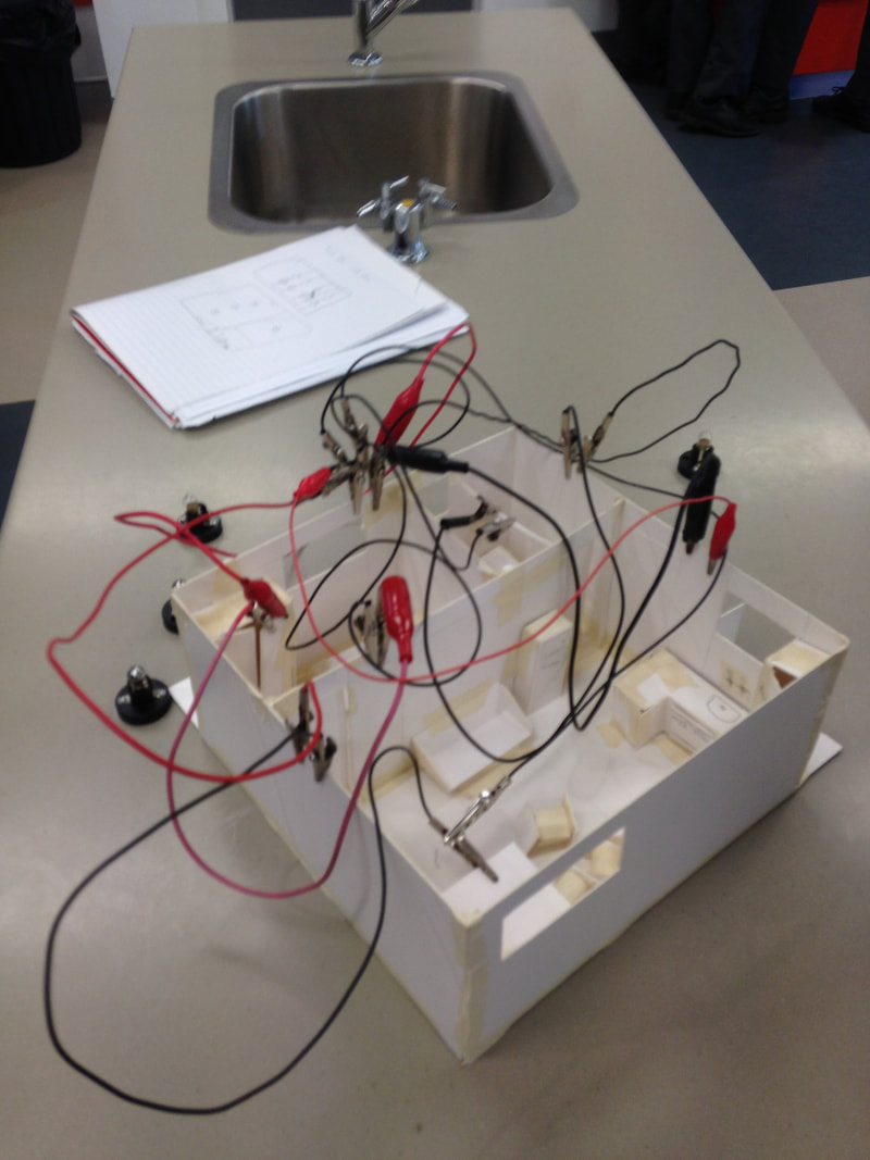  Lesson Summary:
Deeper understanding of final wire placements. Trialed how the system works. Aim: To complete floor plan and to add a circuit diagram over the floor plan. In the below image you can see how the parallel circuit is going to run. It has 5 switches (In the right image the beige circles or ovals), 4 LED lights , 1 fan motor.
Aim: To complete into-science activities from last week if unfinished and to start making a floor plan of our house. Stem Question: What is Voltage and Current? Voltage, also called electromotive force, is a quantitative expression of the potential difference in charge between two points in an electrical field. The greater the voltage, the greater the flow of electrical current (that is, the quantity of charge carriers that pass a fixed point per unit of time) through a conducting or semiconducting medium for a given resistance to the flow. Current is a flow of electrical charge carriers, usually electrons or electron-deficient atoms. The common symbol for current is the uppercase letter I. The standard unit is the ampere, symbolized by A. One ampere of current represents one column of electrical charge (6.24 x 10¹⁸ charge carriers) moving past a specific point in one second. Physicists consider current to flow from relatively positive points to relatively negative points; this is called conventional current or Franklin current. Electrons, the most common charge carriers, are negatively charged. They flow from relatively negative points to relatively positive points. Electric current can be either direct or alternating. To summarise Voltage is the potential difference in charge between two points in an electrical circuit. In other words, the voltage is the 'push' that makes the electrons move. Current is the rate of flow of electrical charges. In other words, if a few electrons are moving, the current will be low. If lots of electrons are moving, the current will be high. Lesson Outline: Because I had finished my Into-science activities last week, I decided to start creating a floor plan of our house. I first took a photo of our house and the using SmartDraw, I made a floor plan for it. In tomorrows lesson, I will create a circuit diagram and super-impose that over the top of the floor plan.   Lesson Summary:
I Created a floor plan for our house I revised what current and voltage is. |
AuthorWrite something about yourself. No need to be fancy, just an overview. ArchivesCategories |
|||||||||||


 RSS Feed
