 Lesson 1 Simple Circuits: In a simple series circuit everything is connected in one loop. That means that there are no points where a current can split or join (called junctions). Circuit diagram represents an actual electrical circuit through the use of signs and symbols.   Rules for a circuit diagram: 1. Use correct symbols - Each component of an electrical circuit has a designated symbol to represent it. A component is: a wire, battery, switch or light bulb 2. Wires are represented by straight lines. - How: Use a ruler. 3. All wires have to be connected without gaps. 4. The length of the wires doesn't have to represent the true length of the wires.  Lesson 2 Transformer The transformer converts voltage of around 240 volts to a much safe 2-12 volts. Outputs and Inputs DC - Direct Current AC - Alternating Current 
0 Comments
Stem Question 1: How can we construct a series circuit that has two functioning lights and a switch? By looking at the diagram below, we can see that when the switch is closed, the electrons will flow around the circuit and the light will glow. This is just one series circuit that allows two light bulbs to work.  Stem Question 2: Why do we use electrical diagrams? We use electrical diagrams because they are very easy to understand because they have no words and use international standard symbols. This allows them to be used anywhere and also be understood anywhere. Electrical diagrams can also show all types of circuits so they can be used for lots of different applications. Electrical diagrams help electricians when sketching up the lighting plans for buildings. Stem Question 3: How can a circuit be made that allows two bulbs to be switched on and off independently? By creating a parallel circuit with a switch and one light on each branch (as in the image below), each light can independently be switched on and off. This allows people to have lights on in one room but not the other.   What Happened in the lesson: This lesson we were revising electrical circuits in preparation for next week when we start making our ouse circuit. What is needed for an electrical circuit to work? - a source of energy - a complete loop - a component - no short circuits We also looked at how to draw overlapping and connecting wires in circuit diagrams (to the left). What are these objects and saying and what do they mean: Ammeter: Used to measure Amps (current) and it is connected in series with the component. Voltmeter: Used to measure Volts (push) and it is connected in parallel with the component. Conventional Current: It is how scientists thought electricity works before they discovered electrons. Conventional current says that particles flow from positive to negative or from high density to low density. This is actually not how electrons flow. They actually flow from negative to positive.   Lesson Summary:
Learnt about the difference between Conventional flow and Electric flow. How to draw wire that overlap or connect. What an Ammeter and Voltage Aim: To construct Parallel Circuits. I will show you images from Izaak's blog because his writing is neater and easier to read.  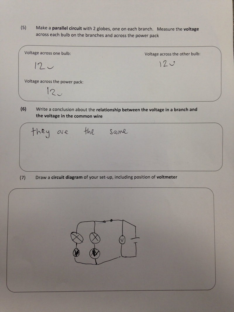 Lesson Summary:
Constructed parallel circuits Recorded amps and volts Aim: To complete Electrical circuits unit in into science. This lesson we were looking at constructing electrical diagrams and circuits. Below are some images from the lesson.    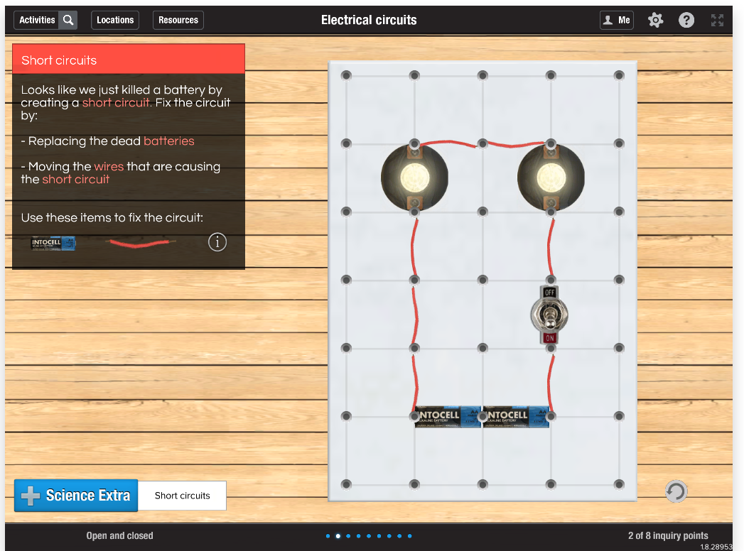  Lesson Summary:
- made circuits on into-science - revised symbols for electrical parts |
AuthorWrite something about yourself. No need to be fancy, just an overview. ArchivesCategories |
||
 RSS Feed
